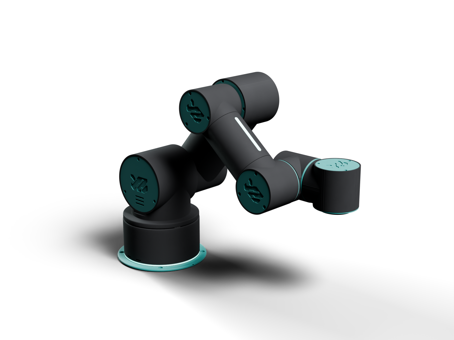
YZ 1-50 · Research platform

Six axes.
Printed. Open.

A desktop research arm built to be understood: belt-driven at the shoulder, modular at the wrist, printed in PLA, and documented as it is made.

Read the research See it come apart
6axes
500mmreach
100gpayload
6×STS3215
Scroll
01In numbers

What it reaches, what it lifts.

The YZ 1-50 bent over a small part on the table, its flange just above it, strips green
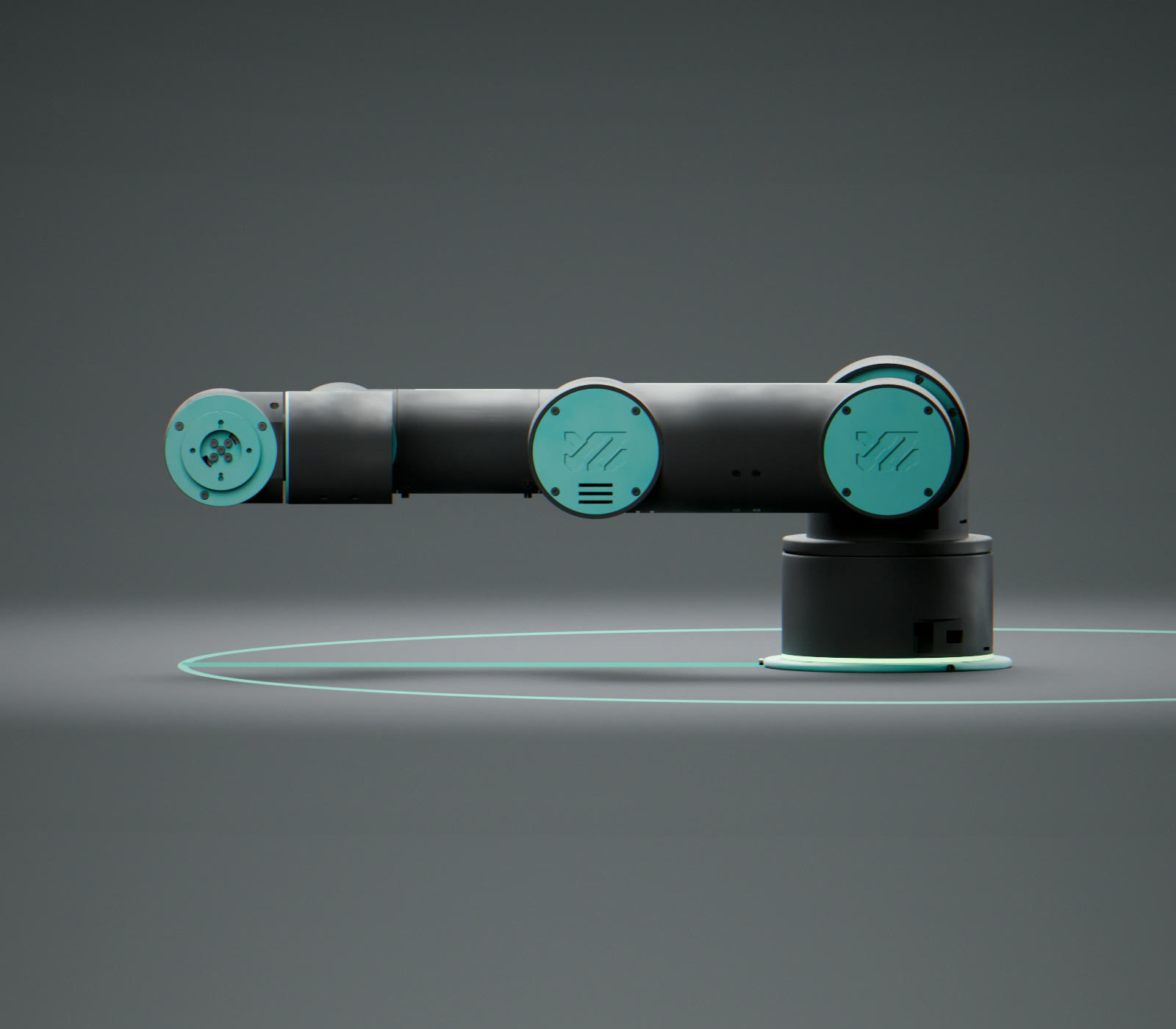
0mmof reach, nominal: the radius of the ring on the floor below. The flange face, arm straight out, is 490 mm from the base axis
0gat the flange, tool included: the 84.5 g parallel gripper and the part in its jaws
Side view of the arm straight and level, its flange face at the tip, above a 500 mm ring drawn on the floor round the base
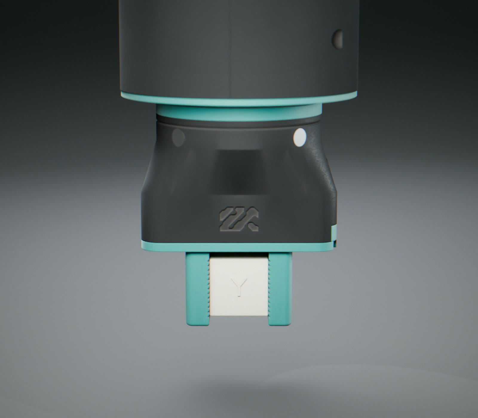
Close up from the side: the parallel gripper on the wrist, pointing down, its engraved logo toward the camera, a 20 mm printed calibration cube held between its two teal fingers
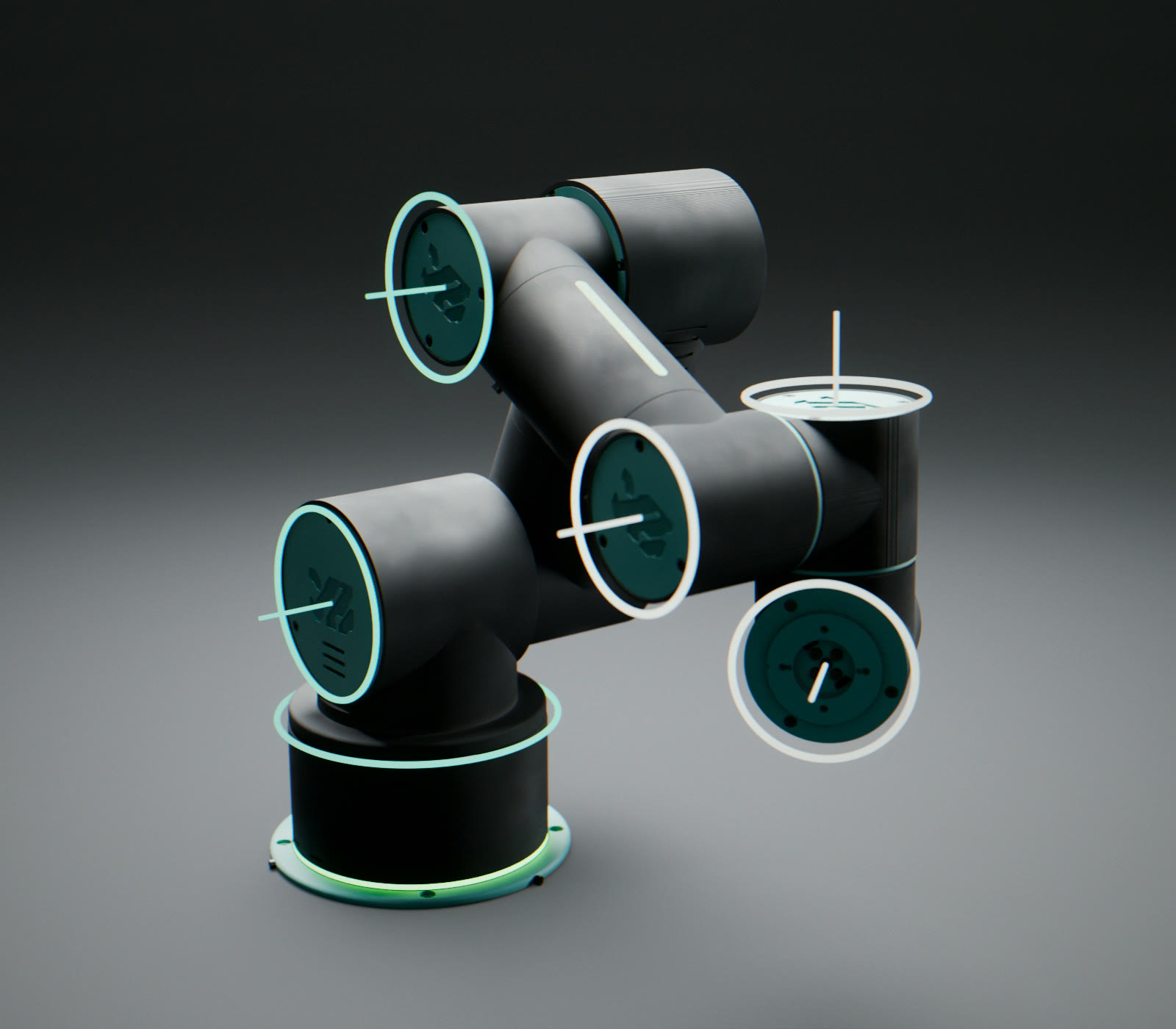
0axes: 1 base, 2 shoulder, 3 elbow, on belts (teal); 4, 5, 6 the wrists, one module three times
The six joint axes drawn through the arm as teal rings and lines
6:1at the shoulder: 15 teeth on the servo, 90 on the arm, one 300 mm belt between them
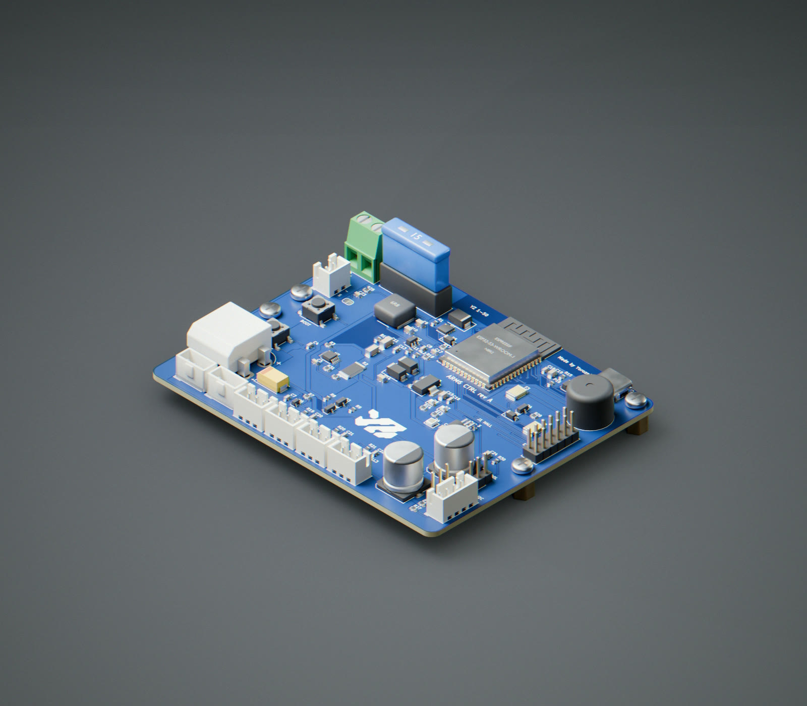
The ARM6 CTRL controller board, blue, on four brass standoffs, in an isometric view: the ESP32-S3 module, the white XT60 power input, the blue 15 A blade fuse, the servo bus headers, the 5 V buck's inductor, the USB-C port and the row of sensor and strip connectors
0custom board, designed for this arm, drives all of it, in place of five bought modules: the ESP32-S3 (1); 12 V in on an XT60 (2) through a 15 A fuse (3); the servo bus (4), its current measured; a 5 V, 3 A buck (5); USB-C (6); the strip, sensor and E-stop plugs (7). Rev A, not built yet.
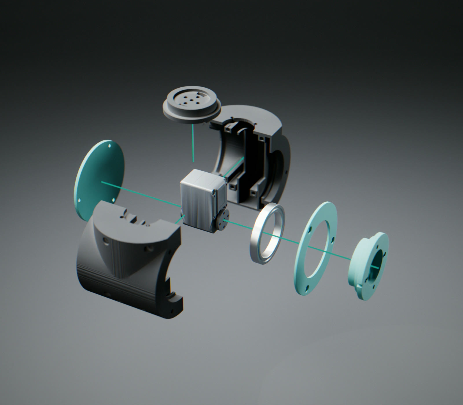
0parts in wrist 3: 1 cap, 2 hub, 3 and 8 the link halves, 4 servo, 5 bearing, 6 retainer, 7 flange. 79 in the whole arm.
Wrist 3 taken apart: hub, the two link halves, servo, bearing, retainer, flange and cap, with their screws
02Platform

One flange. Many tools.

The arm ends in a Ø56 flange with its pins on the 45° diagonals. Everything that bolts to it is a project of its own, and this is the order they are coming in.

Shipping
YZ 1-50 arm, rendered

YZ 1-50 arm

The platform itself. Six STS3215 servos, three belt stages, a 100 g payload at the flange, and a teach pendant that solves, checks and drives it.

Ø56 flange · pins at 45°
Prototype
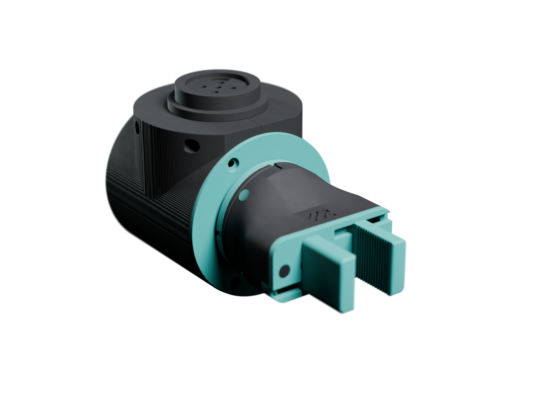
The parallel gripper on the wrist 3 flange: matte black body, teal lid and two teal fingers, rendered from its Rhino model

Parallel gripper

Two serrated fingers on one MG90S: a 12‑tooth pinion drives two racks the opposite ways, opening 0 to 40 mm with about 25 N at the rack. Printed in PLA, 84.5 g all up, it slides onto an adapter that stays on the flange.

0–40 mm · 84.5 g · MG90S
Planned
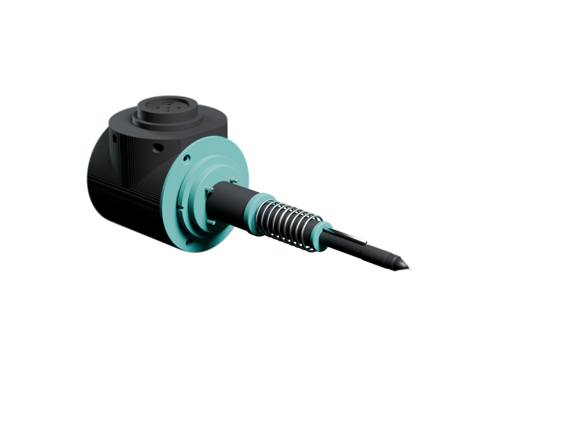
Writing tool, rendered

Writing tool

A sprung pen holder for plotting and handwriting: constant pressure through the pendant's path planner, on paper or a tablet.

Writing
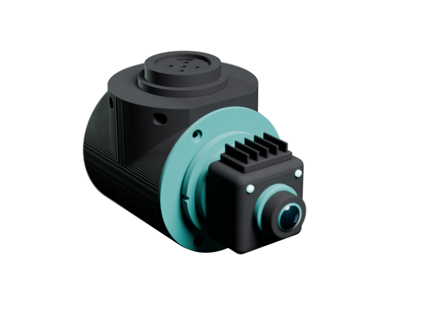
Planned
Vision module, rendered

Vision module

A camera on the wrist so the arm can see what it is doing: visual servoing first, then picking from a table it has not been told about.

Seeing
03Light strips

The strips say what the arm is doing.

Three strips: a halo in the foot, one along the upper arm, one along the forearm. Here the arm runs one short program through every mode they show, and the box beside follows along.

04Specifications

The numbers, as built.

Link lengths and the part count are read live from the same model the site draws, so this table cannot drift from the arm.

Axes
6
Reach
500 mm nominal; 490 to the flange face with the arm straight out and the wrist in line (492 with the wrist turned out)
Payload
100 g at the flange, tool included
Upper arm
…
Forearm
…
Shoulder height
…
Servos
6 × Feetech STS3215, 12 V bus
Reductions
J1 3:1, J2 6:1, J3 4:1 on HTD 3M belts; J4 to J6 direct
Wrist travel
J4, J5 ±180°; J6 ±360°
Controller
ESP32-S3, bus servo adapter, 12 to 5 V buck
Material
PLA, 2.4 mm walls, 0.20 mm layers (0.12 on the lids)
Light strips
Foot halo, upper arm, forearm; 42 WS2812B LEDs on one data line, bench-tested
Parts
…
Tool flange
Ø56, two pins on the 45° diagonals, four M3 inserts on the axes
Power
12 V, 5.5 × 2.5 mm jack
00 / 06

YZ 1-50, assembled

Scroll to take it apart, one module at a time, from the pedestal to the flange.

05Anatomy

Scroll. It comes apart.

06On video

The build, as it happened.

Assembly and tests, one axis at a time, on YouTube. Nothing loads from YouTube until you press play.

    07Research log

    What changed, and why.

    Every decision on the YZ 1-50 is posted as it is made: the mechanics, the printing, the firmware, the interface, the film. The five latest are here.

      All research entries